

Ultra high strength steel 300M is increasingly being used due to its excellent material properties, but this material has high processing difficulties. By studying the processing technology of rough and fine processing of this material, mastering scientific and reasonable processing parameters and methods, the product of this material can be stably produced. Meanwhile, its processing technology can be referenced and used by other similar materials, which has promotional significance.
The aviation industry is described as the "flower of modern industry", which is an important indicator of a country's technology, economy, national defense strength, and industrialization level. On the one hand, it is the foundation of national defense security, and on the other hand, it is also an important pillar driving the country's economic development. As a national treasure, the aviation manufacturing industry combines the typical characteristics of high-tech industry and advanced manufacturing industry, and has received high attention and priority development from countries around the world.
The Development Trends of Materials for Aviation Parts
In the structural design of advanced civil aviation aircraft both domestically and internationally, in order to meet the requirements of long service life, easy maintenance, and lightweight of aircraft, the structure of the base parts is developing towards integration, complexity, and thin-walling. Therefore, more and more integrated structural designs are being adopted, and new materials are being used to improve the structural strength of the aircraft.
With the continuous development of material technology, forging technology, and processing technology, the use of ultra-high strength alloy steel to manufacture the main load-bearing components of large aircraft landing gear has become an inevitable choice. At present, the most widely used landing gear materials abroad are ultra-high strength alloy steel, such as 35NCD16 from France, 30XCH-2A from Russia, and 300M from the United States. High material strength can make landing gear lightweight, and weight reduction has always been an important indicator pursued in landing gear design. At the same time, materials should have excellent comprehensive performance to ensure the reliability of landing gear operation.
300M Material properties
(1) The 300M ultra high strength alloy steel with metallic properties is an important medium carbon nickel chromium molybdenum steel in the American aviation industry, and its metallic composition is shown in Table 1.
Table 1 Chemical Composition of Materials (Mass Fraction) (%)
| C | Si | Mn | P | S | Cr | Mo | Ni |
| 0.40-0.45 | 1.45-1.80 | 0.65-0.90 | 0.01 | 0.0015max | 0.70-0.95 | 0.35-0.50 | 1.65-2.00 |
Compared with other metals, the chemical, physical, and mechanical properties of this metal have its own characteristics, which can be summarized as follows:
① Ultra high strength. Ultra high strength steel is a type of steel with low carbon and low alloy content. Compared with non alloy steel, it has higher strength and is inherently known as low alloy ultra-high strength steel.
② High yield strength. Compared with non-alloy steel, low alloy steel has a higher yield point, so under the same load, the weight of the parts can be reduced by 20% to 30%.
③ Good plasticity and toughness. The proportion of alloying elements in low alloy steel is relatively low, and it has good plasticity and toughness.
④ High hardenability. The alloy material contains elements such as Ni, Cr, Mo, etc., which makes the undercooled austenite of the steel quite stable. After air quenching, martensite and bainite structures can be obtained.
(2) Material processing performance analysis: This material generally has two heat treatment states, namely normalizing+tempering and quenching+tempering. The corresponding hardness of these two states is shown in Table 2.
Table 2 Material Hardness
| Condition | Hardness Unit | ||
| HV | HBS/HBW | HRC | |
| Normalization+Tempering | N/A | 302 Max | 31Max |
| Quenching+Tempering | 590-630 | 555-590 | 52-55 |
From Table 2, it can be seen that the material has good hardness, and its tensile strength value is also very high. It is precisely because of this reason that it is very difficult to machine and belongs to the category of difficult to machine materials, mainly manifested in the following aspects:
① High cutting force. Due to the high hardness and strength of materials, high atomic density and bonding force, high fracture toughness and persistent plasticity, the cutting force is large during the cutting process, and the fluctuation of cutting force is also relatively large.
② High cutting temperature. During the cutting process, alloys consume a large amount of cutting deformation power, generate a lot of heat, and concentrate a large amount of cutting heat in the cutting zone, forming a high cutting temperature.
③ There is a strong tendency for work hardening. Alloy has the characteristics of high plasticity and toughness, coupled with a high strengthening coefficient, which generates huge plastic deformation under the action of cutting force and cutting heat, resulting in work hardening; Under the action of cutting heat, the material absorbs atoms of elements such as hydrogen, oxygen, and nitrogen in the surrounding medium to form a hard and brittle surface, which brings great difficulties to cutting.
④ Excessive tool wear. When cutting, the cutting force is high, the cutting heat is high, and the direct friction between the tool and the chip is intensified. The tool material has an affinity with the workpiece material. In addition, the presence of hard points in the material and severe work hardening phenomenon make the tool prone to adhesive wear, diffusion wear, grinding wear, convenient wear, and groove wear during the cutting process, causing the tool to lose its cutting ability.
⑤ Chips are difficult to handle. The material has high strength, plasticity, and toughness, and the chips produced during cutting are wrapped in ribbons, which is not only unsafe but also affects the smooth progress of the cutting process and is not easy to handle.
⑥ Cutting deformation is significant. During the processing of alloy materials, the cutting temperature is high, the plasticity is high, and thermal deformation is prone to occur during processing, making it difficult to ensure some precise dimensions and shapes.
Sichuan Huitai Special Metals Co., Ltd. has been committed to processing ultra-high strength steel 300M for a long time. The tensile strength level of this material reaches 1900-2100MPa. After continuous testing and cutting, using specific processing tools, a stable processing plan has been summarized to ensure stable and efficient production of products. The processing technology of this material is introduced from three aspects: rough machining, turning machining, and milling machining of 300M. Among them, turning and milling machining of 300M belong to the category of precision machining.
300M rough machining
The rough machining of 300M generally occurs before the final heat treatment. At this time, the material is in a normalized+tempered state, with a maximum hardness value of 31HRC. The hardness is low, has a certain viscosity, and is not easy to break chips. In order to reduce the cutting allowance for precision machining, as much material is removed as possible during rough machining.
(1) The commonly used tool for rough turning is WIDIA's CNMP120408, as shown in Figure 1a, which is suitable for rough machining. Due to the softness of raw materials, in order to better break chips and ensure high processing efficiency, their processing parameters are generally larger. Its cutting speed is 175~200m/min, cutting depth is 1.5~2mm, and feed rate is 0.2~0.4mm/r. After processing, the generated iron filings are small and the chip breakage is good.
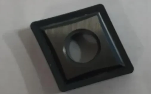
a) Outer turning tool

b) Chips
Figure 1 External Turning Tools and Chips
(2) Deep hole machining is a fast material removal machining method that can be selected from U-drilling and deep hole machining, with slight differences between the two methods.
1) Use U-drill for machining. Due to the high power required for using U-drills and the relatively large diameter of the processed holes, horizontal machining centers are generally chosen. When using drilling, the cutting speed of the tool is between 40-60m/min, and the single tooth cutting amount of the tool is between 0.15-0.3mm. Under these processing parameters, the generated chips will be slightly thinner, but a better chip breaking state can also be achieved. Figure 2 shows the U-drill machining used on a horizontal machining center and the generated chips.

a) U-drill

b) Chips
Figure 2 U-drill and chips
2) Deep hole drilling processing. When using a deep hole drill for processing, special attention should be paid to the fracture mode of the chips. Long and thin chips are particularly prone to blocking the cutting tube of the deep hole drill tool, causing chips to be unable to be discharged. In general machining, the cutting amount per tooth is 0.2-0.4mm. While ensuring sufficient tool strength and machine load, try to control the cutting amount per tooth above 0.3mm. This will make it easier for iron chips to break and produce ideal chips. The machining tools and chips are shown in Figure 3.

a) Deep hole drilling tools

b) Chips at a cutting amount of 0.3mm per tooth
Figure 3 Deep hole drilling tools and chips
300M turning machining
Turning is generally divided into outer circle turning and inner hole boring. The difficulty of turning is lower than that of boring, and the tool strength during turning is better than that of boring, making chip removal easier and cooling more sufficient. In order to ensure the machining quality of parts, it is generally divided into rough and fine machining.

Figure 4 Precision machining of turning blades
(1) When rough machining the outer circle with external turning, the linear speed is 90-120m/min, the cutting depth is 0.3-0.8mm, and the feed rate is 0.1-0.2mm/r. When using this tool for machining, it can be ensured that there is only one tool tip point in contact with the outer circle of the part, which can reduce cutting force and cutting heat. The tools and chips used for machining the outer circle are shown in Figure 5.

a) Outer turning tool

b) Chips
Figure 5 External Turning Tools and Chips
From Figure 5, it can be seen that the generated chips are darker in color and longer in length, forming a curly shape. This is because after the final heat treatment, the tensile strength of the material is greatly improved, and a large amount of cutting heat is generated during the machining process, which is not easy to break chips.
When precision machining the outer circle, the linear speed is 90-120m/min, the cutting depth is 0.05-0.1mm, and the feed rate is 0.05-0.1mm/r. Such processing parameters can ensure that the surface of the precision turning outer circle is very smooth, and the generated chips are shown in Figure 6.

Figure 6 Fine turning chips
(2) There are three issues to pay attention to when machining inner holes: first, there should be good cooling, sufficient coolant, and the concentration of coolant should be ensured; Secondly, it is necessary to ensure good chip removal and avoid the occurrence of chip squeezing and cutting; The third is to ensure that the cutting tools have good rigidity.
In order to achieve good chip removal, rough machining usually adopts segmented boring method when boring inner holes, which is divided into several segments based on the total length of the inner hole of the part. During segmented boring, the generated chips can be discharged in a timely manner, avoiding the accumulation of a large amount of chips in the inner hole and causing the tool to deviate. The boring method is shown in Figure 7. When boring inner holes, it is necessary to use shock-absorbing tool holders and large diameter tools. The length of the tool should match the length of the part, and the tool should be slightly longer than the part. This can maximize the rigidity of the tool, avoid vibration and cutting, and make the surface of the inner hole smoother. The tools used for boring holes are shown in Figure 8. During rough machining, the linear speed is 90~120m/min, the cutting depth is 0.2~0.5mm, and the feed rate is 0.1~0.2mm/r. The generated chips are shown in Figure 9.
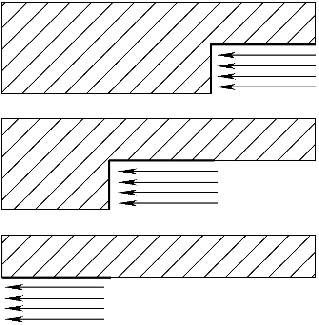
Figure 7 Boring method

Figure 8 Anti vibration knife bar

Figure 9 Rough boring chips
The chips generated by boring are longer than those from the outer circle of the car because their cutting depth is smaller than that of the outer circle of the car, making them more difficult to break and more curly. The processing parameters of precision boring inner holes are similar to those of precision turning outer circles, and the generated chips are also basically similar.
300M milling processing
When designing the machining process, in order to ensure the smoothness of the entire machining process, the final shape milling of the parts is chosen, and the machining features, cutting tools, and machining methods chosen are also different.
(1) Rough machining generally uses machine card type cutting tools, which have high processing efficiency and low cost. Standard blades can ensure the stability of rough machining dimensions. When processing this material, selecting tools produced by Shante can achieve good results. The tool model is R390-020A20-11M, and the blade model is R390-11 T3 31M-KM, as shown in Figure 10. When using this tool for machining, the cutting speed is 100-150m/min, the cutting depth is 0.5mm, and the feed rate is 400-800mm/min. Choosing a too large cutting depth can cause abnormal damage such as blade breakage to the blade. After processing, the chips are shown in Figure 11.

Figure 10 Rough machining tools and blades

Figure 11 Rough milling chips
(2) If the feature size of a small part is small, larger diameter tools cannot be used. In order to increase the tool's lifespan and ensure the machining quality of the part, some machining skills are needed. When processing 300M, it is best to use cycloidal milling instead of layered milling for small-sized features.
Cycloidal milling has many advantages, such as high machining efficiency, low radial cutting force, insensitivity to vibration, and small deviation when machining deep grooves. It has good chip removal performance and generates less heat. It is recommended to be used for processing hard materials and vibration sensitive states. Its processing mode is shown in Figure 12. When using cycloidal milling, the cutting speed can reach 150-200m/min.

Figure 12 Cycloidal milling
(3) When precision machining, it is advisable to choose cutting tools that are as close to the machining size as possible to ensure good rigidity, and coated cutting tools should be selected, as shown in Figure 13. The cutting edge of the tool should be sharp, so that the surface roughness produced can meet the requirements, as shown in Figure 14.

Figure 13 Cycloidal milling
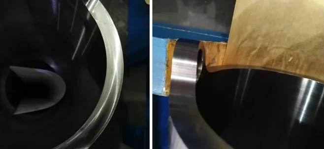
Figure 14 Surface quality after precision machining
Due to the excellent material properties of 300M ultra-high strength steel, its application range has become increasingly wide, but at the same time, it has also increased the difficulty of processing. In the production process, it is necessary to choose specific cutting tools and reasonable processing parameters to avoid rework or scrapping of parts. With the development of emerging processing technologies, it will inevitably make processing such materials relatively simple and easy, while also requiring continuous summarization and accumulation of processing experience.
Aviation components can work in harsh environments, so special attention should be paid to product quality. Minor defects in mechanical processing can have adverse effects on subsequent special processes. To avoid this potential risk, quality control must be strictly enforced during the processing.


